
Recently on bentleyuser.org...

© bentleyuser.org 2026
Printed from www.bentleyuser.org © TMC Publications (UK) Ltd 2010
MicroStation 101 - The Anatomy of a V8 file: File settings vs. Model Settings
by Karen Fugle - 14 April 2005
![]() Model? File? Settings for each? Im confused already!
Model? File? Settings for each? Im confused already!
Ok, Lets take a step back and have a quick comparison look between a Dgn and a DWG and we can see where how we use the term model in their setup.
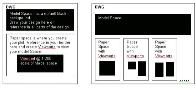
A Dwg is made up of two parts: Model space and Paper space. The Model space is where you draw your design. The paper space is where you reference in your drawing border and create what are called "view ports". A view port kind of punches a hole in the paper space, to look through to the design in the model space. Each viewport you create can zoom into a part, or whole, of the design at different scales. A DWG can only have one model space but can have multiple Paper spaces.
Ok, so what about a DGN?
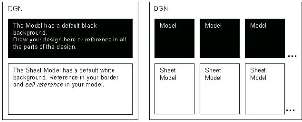
In a similar manner a V8 Dgn may consist of multiple spaces or models as Bentley terms them. A DGN consists of at least one model the Default Model. The file may contain any number of additional models, but unlike AutoCAD these do not only have to be Paperspace, they may be either Design Models or Sheet Models. Draw your design in the Model or reference the different parts of the design into the model. The Sheet Model is where you reference in your drawing border and self reference in the model, to create your layout or plot. A DGN can have multiple models and multiple Sheets.
So how do I create another model and a sheet and...
You can find out more about how to create models and sheets in the 101 article called Sheet Layouts. A lot of companies still only work in the one model (the Default Model) as multiple users cannot access different models within one Dgn.
Now lets look close up at how the settings are affected.
The Anatomy of a V8 file: File settings vs. Model settings
Ever been confused about which settings are File based and which are Model based? Heres a diagram that will show you the levels of settings within a single file.
The Anatomy of a V8 file: File settings vs. Model settings Q and A
Q: I have a set of consultant's drawings in which the symbology is incorrect. Is there an easy way to correct the symbology without opening every file and changing it individually?
A: Create a new file. Check the View Attributes are set with the tick in Level Symbology. Reference in each consultant file into a separate model (copy the first model repeatedly to create the extra models). In Level Manager, go to """"All levels"""" in the tree view and (all levels in all models) correct the override symbology for each level. Level Manager is a global setting so you only have to do this once.
OR
A: Set the symbology right for the first reference file. Right click and select all levels. Right click and copy. Open level Manage in the next model. Right click and paste. Continue for each model.
Q: Now I want to turn off specific levels in all of those reference attachments. How can I do this without having to go into each model and setting the view display?
A: Get your level settings (and View Attribute settings) right in the first model. Create a View Group (Manage View groups dialog and Create new Group.) Call it Reference Levels>ok. It stores the configuration of all your windows and stores all the levels displayed in each of those views and the View Attribute Settings. In your other models and choose that view group. Voila!
Q: I don't use models; I want to turn on and off the same levels across a series of design files.
A: Get your level settings right in the first dgn. Then create a Saved View (Utilities>Saved Views or Top left Bentley window logo - view save/recall). Go into your next file and using the same toolbox Import Saved View. Providing the same references are attached when you hit Apply the right levels will be switched on and off (but for v 08.05.02.27 see Bug Alert below).
Q: I want to create variations of my first model and I want the colour symbology to be different in each. Symbology is File specific, so how can I make it model specific without performing a save-as on the file?
A: Reference in the first model into your second model. Then use Level Manager to alter the overrides.
OR
A: It depends on how you want to alter the symbology. You could repeatedly reference in your first model into your second model. Then use the level display to turn on/off levels required to be in the same colour. Or you could use the Settings: Adjust Colours for each reference file to alter the """"Hue fixed for all colours"""" tab.
Q: I want a model from another drawing to be in my file. Can I get it without referencing it in?
A: Use the Models tool (Primary toolbar) and click on the Import Models button. You can import multiple models at once (great for consolidating cell libraries).
Q: I have a corrupt file. I want to copy the contents into a new file and retain all the views and levels so I don't have to reset them.
A: In the corrupt file, for each of your windows, create a Saved View. Click on the B icon at the top left of a window and click View Save/Recall. In the Saved Views dialog click on the Save View tool to save each view with a description. In your new file open the same dialog but click on Import Saved View. Match the name with the correct view number and Apply (but for v 08.05.02.27 see Bug Alert below).
BUG ALERT: In version 08.05.02.27, despite ticking the Levels box in the Saved View Dialog, there is a bug that prevents the views from honouring the level settings in the source file. This is something that Bentley need to address pronto as surely it is a primary function of a saved view to honour these settings! Trouble Report 129285.